Car Trailer Electric Brake Wiring Diagram
Trailer Brake Control Proportional Electric Trailer Brakes Wiring Diagram Australia by Bismillah. Electric Trailer Brake Wiring Diagram The price of a trailer mend by a specialist can value nearly 90 an hour or so.

Trailer Electrical Wiring Australia Trailer Wiring Diagram Trailer Light Wiring Car Trailer
White Pin to your floor.

Car trailer electric brake wiring diagram. I have included a diagram for you. A wiring diagram is a streamlined conventional pictorial representation of an electric circuit. They also provide a wire for a ground connection.
As the name implies they use four wires to carry out the vital lighting functions. The four wires control the turn signals brake lights and taillights or running lights. Click on the image below to enlarge it.
Only the blue brake and white ground wires are different. Just like just about anything regular upkeep checks may also help in preventing some important troubles. Heres the diagram for 7-pin connector.
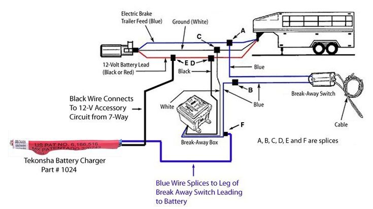
This Trailer Breakaway Box Wiring Diagram version is much more acceptable for sophisticated trailers and RVs. Wiring Diagram Images Detail. White Pin for the floor.
4-Way trailer connectors are typically used on small trailers such as boat snowmobile utility and other trailers that that do not use brakes. The first image shows a single axle trailer and the second wiring for Tandem Axles. Wiring Diagram comes with numerous easy to adhere to Wiring Diagram Instructions.
White Pin for the ground. All circuits are the same voltage ground individual component and switches. Heres the diagram for 7-pin connector.
Elecbrakes must be connected to trailer wiring circuits as outlined in the wiring diagram. Trailer Wiring Diagrams Trailer Wiring Connectors Various connectors are available from four to seven pins that allow for the transfer of power for the lighting as well as auxiliary functions such as an electric trailer brake controller backup lights or a 12V power supply for a winch or interior trailer lights. If not it is still a terrific knowledge to have for when problems happen to your beloved car.
This Wiring Electric Trailer Brakes Diagram model is more acceptable for sophisticated trailers and RVs. 4-way trailer connectors are. Choose a connector that has the required number of pins for the functions.
Assortment of electric trailer brake wiring schematic. I recommend using 12-gauge wire 12-1-1 for the. This car is designed not just to travel one place to another but also to carry heavy loads.
Electric Trailer Brake Wiring Diagram Source. Electric Trailer Brake Wiring Diagram People today comprehend that trailer is a car comprised of very complicated mechanisms. This guide will be discussing electric trailer brake wiring diagramWhat are the advantages of knowing these knowledge.
It may transfer power better therefore the connector is recommended for higher-level electric in the car. I go over all the basics on wiring up your vehicle trailer harness and electric brakes. It may transfer power better so the connector is suggested for higher-level electric in the car.
Typical Trailer Wiring Diagram and Schematic The 2 above wire diagrams fit the needs of most trailers. It reveals the parts of the circuit as streamlined forms as well as the power and signal connections in between the gadgets. If the trailer wiring is running down the left side of the trailer then we splice the left side brake assemblies into the main electric brake power wire coming from the 7-way connector.
Electric Trailer Brakes Wiring Diagram Australia. It can transfer electricity better hence the connector is suggested for higher-level electric in the auto. Its meant to aid all of the common user in building a correct program.
Click on the image below to enlarge it. If this is correct you will need to connect one of the wires to the brake controller output wire on your trailer connector and the other wire will need to be grounded to a clean metal surface on the trailer. Tekonsha Trailer Brake Control Proportional Electric Trailer Brake Wiring Diagram.
Trailer wiring diagrams trailer wiring connectors various connectors are available from four to seven pins that allow for the transfer of power for the lighting as well as auxiliary functions such as an electric trailer brake controller backup lights or a 12v power supply for a winch or interior trailer. This Wiring Diagram For Electric Trailer Brake Controller model is far more acceptable for sophisticated trailers and RVs. Other cost-free preventative actions might be used to lessen the chance of challenges in the future especially for by far the most adventurous of us who wish to stay.
The first diagram is a simple set up of two brake lights two indicators and two side lights. Hopefully the post related to Electric Trailer Brakes Wiring Diagram Australia will be assisting driver to design their own trailer cables better. These guidelines will likely be easy to grasp and use.
Heres the diagram for 7-pin connector. The Service Brake circuit must be disconnected from an existing trailer plug. The second diagram shows two brake lights two indicators two side lights and a fog light.
Ensure it is sealed off and cannot create a short circuit with any other wire or the chassis. Here are two wiring diagrams for the 7 pin N type trailer electrical plug. Using this guidebook you will be capable to determine how every element needs to be.
2 axle trailer brake wiring diagram How Much to Install Electric Brake Controller Fresh Wiring Diagram Trailer Brake Tekonsha P3 Wiring Diagram. We then run a jumper wire from the electric brake power wire to the right side brake assemblies see photo.

Pin By Jeroen Bent On Van Trailer Light Wiring Trailer Wiring Diagram Car Trailer

33 Wiring Diagram For Electric Brake Controller Bookingritzcarlton Info Trailer Light Wiring Trailer Wiring Diagram Rv Trailers

Trailer Light Wiring Utility Trailer Car Trailer

Left Brake Light And Turn Signal Not Working On Trailer Towed By 2003 Gmc Sierra Trailer Light Wiring Trailer Wiring Diagram Utility Trailer

Trailer Brake Controller Information Trailer Wiring Diagram Brake Diagram

Electric Brake Control Wiring Trailer Wiring Diagram Trailer Light Wiring Electricity

Wiring Diagram For Trailer Light 4 Way Http Bookingritzcarlton Info Wiring Diagram For Trailer Light Trailer Wiring Diagram Trailer Light Wiring Electricity
Circuit Diagram Pole Travel Trailer Connector Wiring Color Code Trailer Light Wiring Trailer Wiring Diagram Rv Solar Power

How To Install An Electric Brake Controller Trailer Wiring Diagram Electrical Diagram Electricity

Boat Trailer Lights Trailer Wiring Diagram Horse Trailer

Wiring Guides Trailer Light Wiring Trailer Wiring Diagram Utility Trailer

Wiring Diagram For Trailer Light 4 Way Http Bookingritzcarlton Info Wiring Diagram For Trailer L Trailer Wiring Diagram Trailer Light Wiring Flatbed Trailer

7 Pin Trailer Plug Light Wiring Diagram Color Code Trailer Light Wiring Trailer Wiring Diagram Boat Trailer Lights

Universal Installation Kit For Trailer Brake Controller 7 Way Rv And 4 Way Flat 10 Gauge Wires E Trailer Installation Trailer Plans

Wiring Diagram Wiringguides Jpg Fantastic Way Trailer Wire For Trailers Trailer Wiring Diagram Diagram Trailer Light Wiring

Trailer Wiring Diagrams Trailer Light Wiring Trailer Wiring Diagram Car Trailer

Trailer Wiring Diagrams Trailer Light Wiring Trailer Wiring Diagram Utility Trailer

16 Car Trailer Wiring Diagram Nz Trailer Light Wiring Trailer Wiring Diagram Utility Trailer
Trailer Breakaway Switch Smoked Melted When Trailer Was Trailer Wiring Diagram Diagram Trailer
Posting Komentar untuk "Car Trailer Electric Brake Wiring Diagram"